Wardsweb Custom ST-70 Modification and Build


This page documents the build of my custom ST-70 from a stock Dynaco ST-70 stereo amplifier.
I used some of the original parts and fabricated a new chassis and cabinet.

  1. The chassis started with a sheet of .080 5052 aluminum cut 14" wide and 12.5" deep from Westbrook Metals
  2. The stock tube sockets are ceramic w/gold pins Part # 055-534 from Parts Express
  3. The stock hardware is stainless button head socket screws from Fastener Express
  4. The stock power transformer is a new PA060 from Dynakit Parts
  5. The stock choke will be replaced with a new C-354 from Dynakit Parts
  6. The driver board is from Shannon Park’s new ST-70 driver board
  7. The driver board parts are from Mouser Electronics - BOM purchase link
  8. The driver board tube sockets are ceramic w/gold pins Part # 90100 from Angela
  9. The two .1uF coupling caps between the 12AX7 input tube and the 12AU7 phase inverter are .22uF Auricaps Part # C-AUD22-400 from tubesandmore.com
  10. The four .047uF headed to the output tubes off the phase inverter are .1uF Auricaps Part # C-AUD1-400
  11. The big bias pots are 25K ohm 10-15 turn pots and the 10K ohm resistor is a 5K ohm
  12. The 47uf capacitors in the bias supply are 100uF @ 100v Sprague Atom Part # C-SA100-100
  13. The selenium rectifier was replaced with a 1N4004 diode
  14. The multi section capacitor was replaced with separate capacitors:
  • The 1st filter stage directly on rectifier will use a 20uF @ 500V Sprague Atom Part # C-SA20-500
  • The 2nd filter stage on the center tap of output transformers will use a 250uF @ 500V JJ filter can Part # C-EC250-500
  • The 3rd and 4th filter stages (front end) use a 100/100uF @ 500V JJ Dual section can Part # C-EC100X2-500


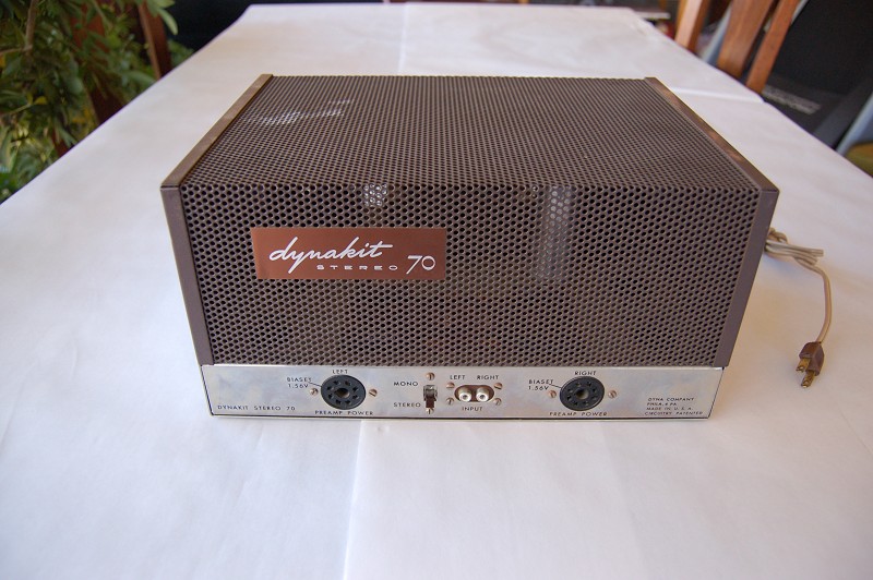
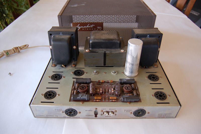
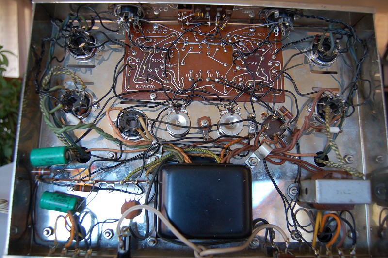
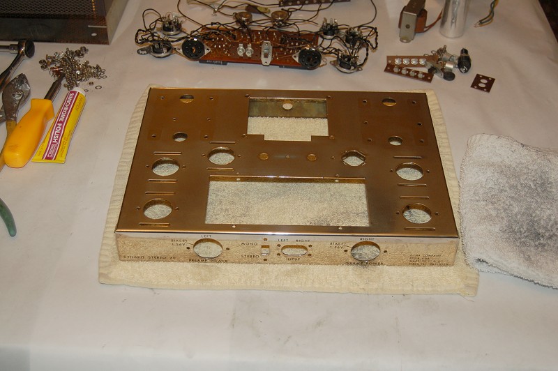
A stock ST-70 unmodified and with original cloth transformers. The output transformers are the first to come out.


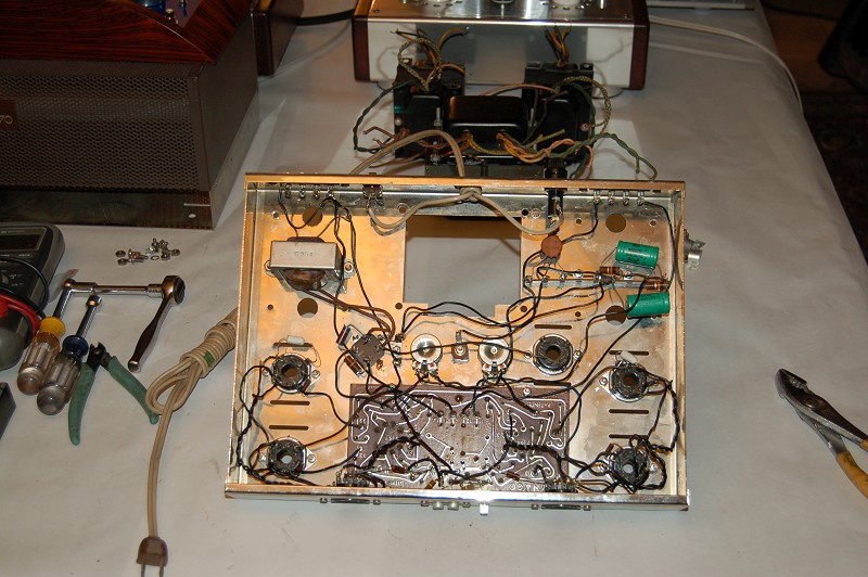
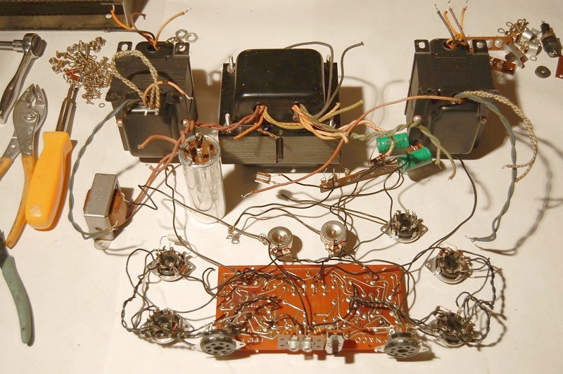
The power transformer comes out and then all the rest. Tired chassis and after some elbow grease and metal polish.


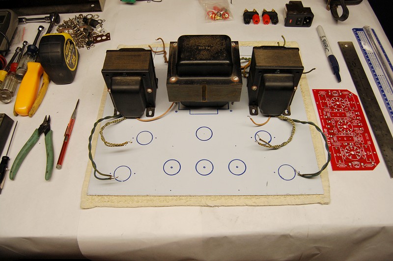
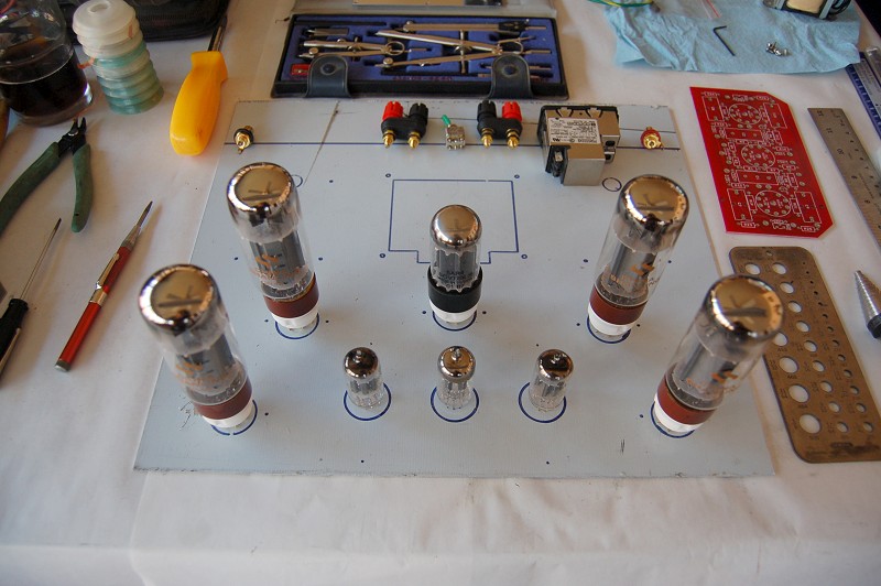
The beginnings of a new layout. The pcb modded slightly for additional clearance to tube sockets.
Only the tube sockets will be mounted on the top of the pcb. The stock vs. Dynakit power supplies.


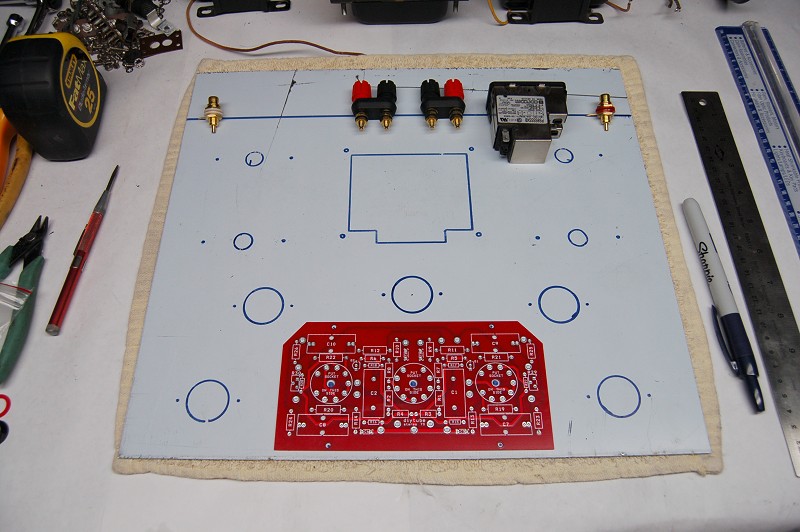
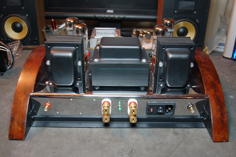
The back of the chassis will bend down at the line. The miniature Honeywell (2TW1-3) switch is for 4/8 ohm taps.
The power entry module is a Corcom (PS0SSSSXB) IEC, fuse, filtering and on/off switch.


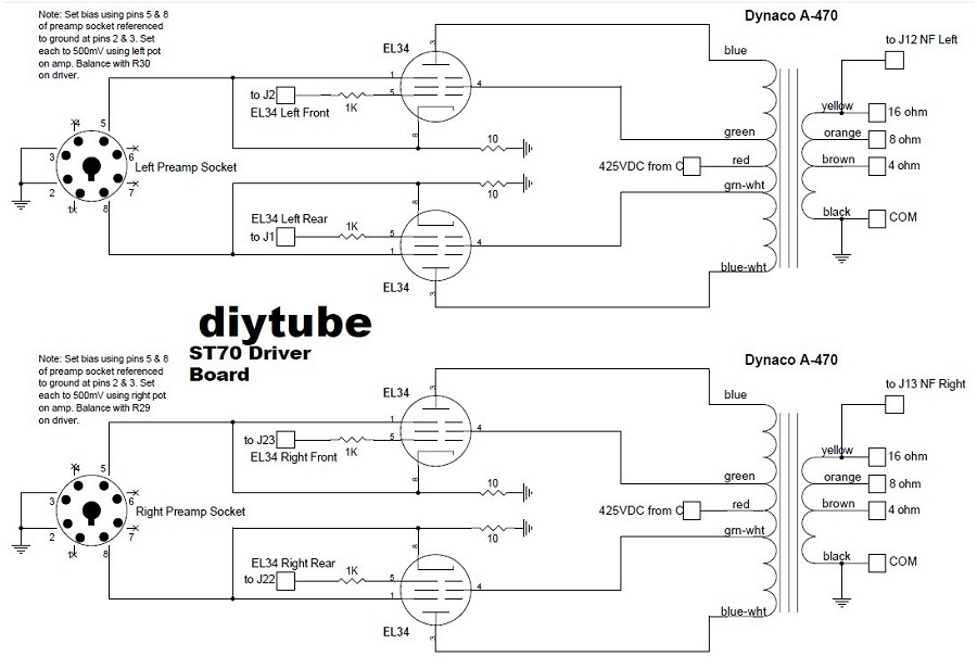
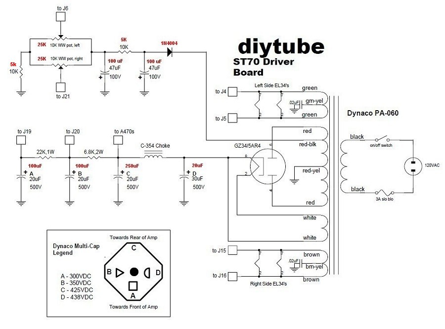
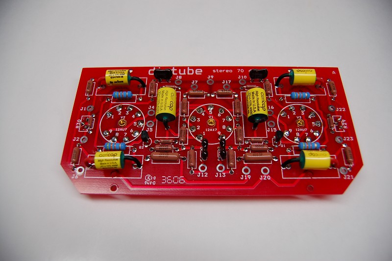
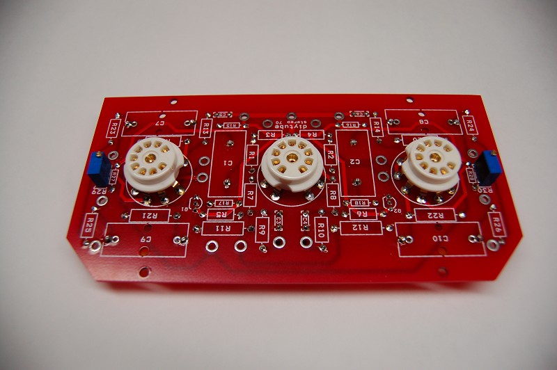
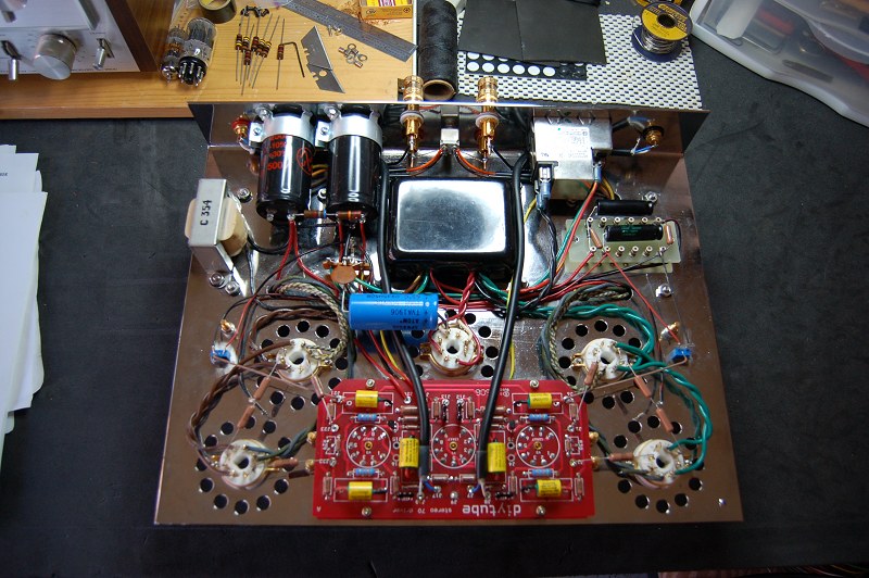
The driver board was stuffed with most parts on the bottom side and only the sockets and pots on the top.
Note much time and care was taken to get the sockets soldered in exactly to match the mounting height of the bias pots.
I only want these top items to come through the chassis.


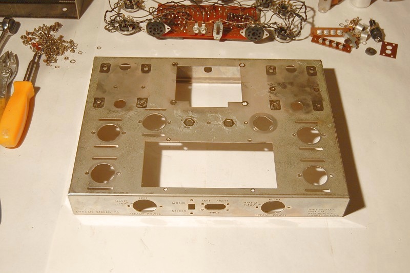
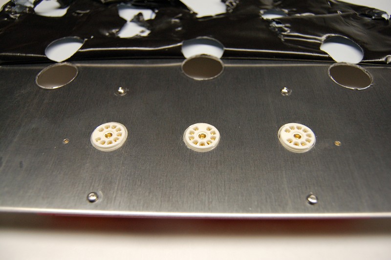
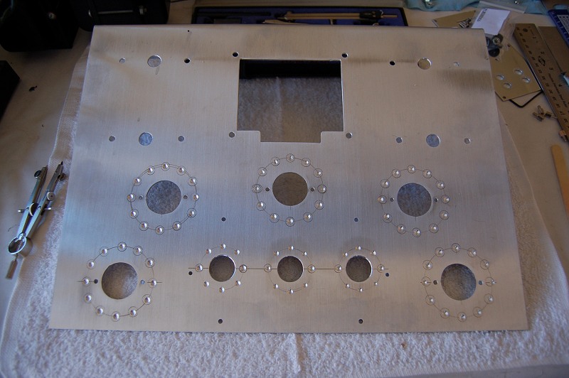
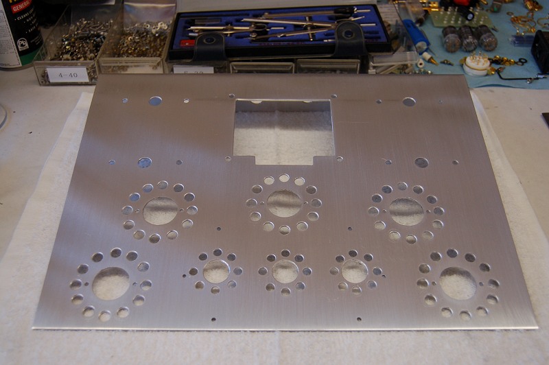
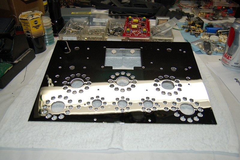
The chassis has been punched, drilled and cut for all mounts.
The next step was a bit of trial and error, as I tried different layouts and routings to determine an optimal design.


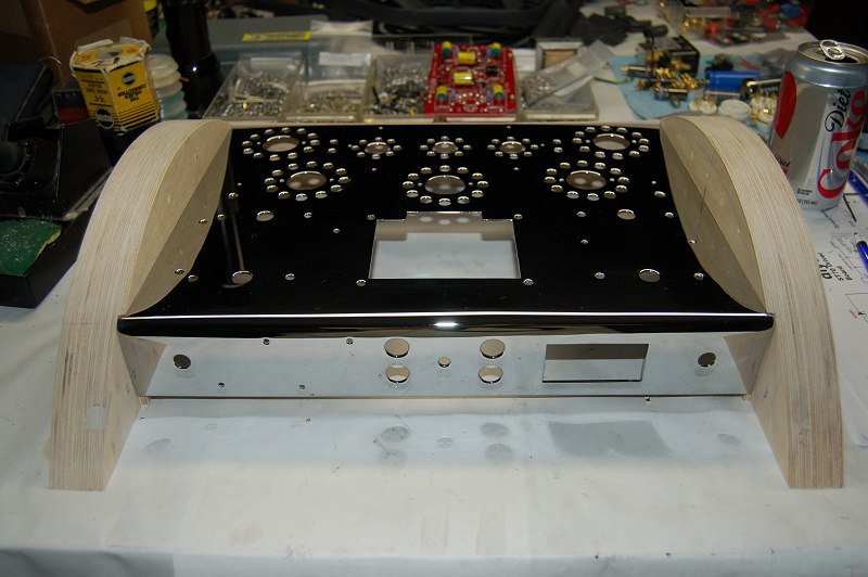
Time for a side track. I decided I wanted the chassis chromed, so I pulled all the parts off and sent it off to the chrome shop.
Then time to start cutting some Baltic birch to complete the new cabinet. I air nailed two sheets and try some different arches.
Once I determine the arch I want, a few passes on the table saw to trim it down.


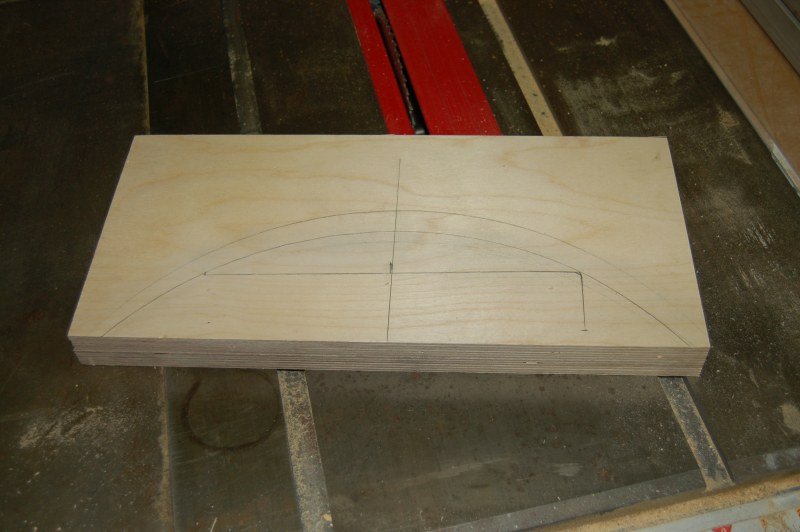
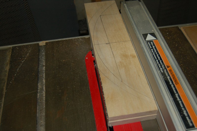
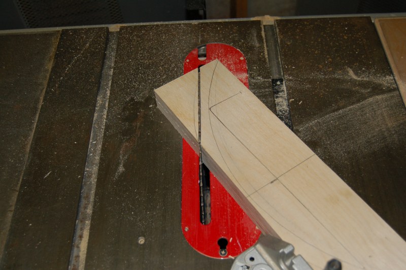
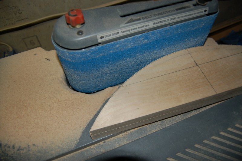
A few more passes to remove excess wood and then on to the table sander.
The front starts with a build up of four layers of Baltic birch and back to the sander.


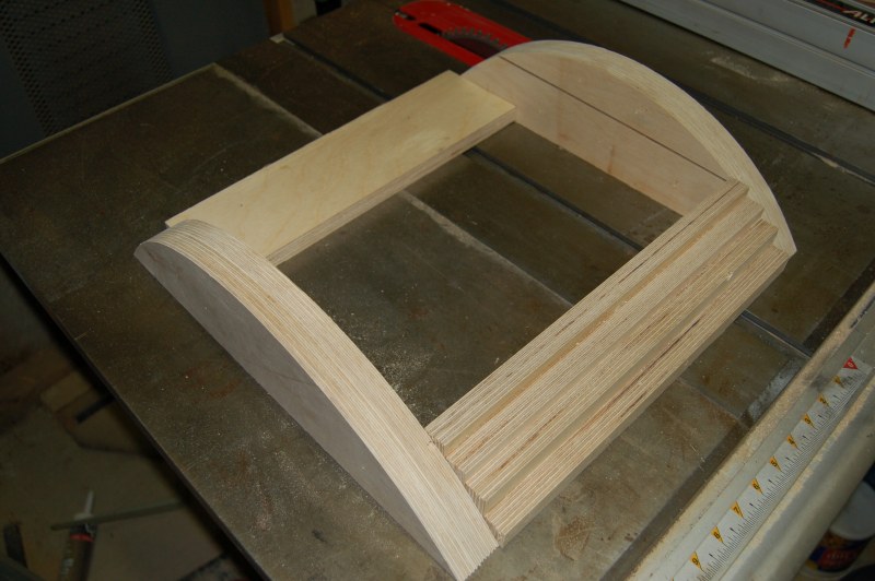
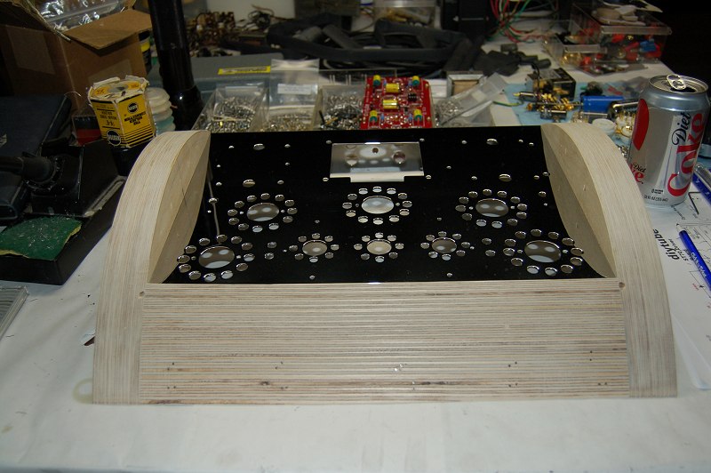
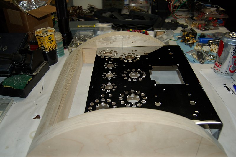
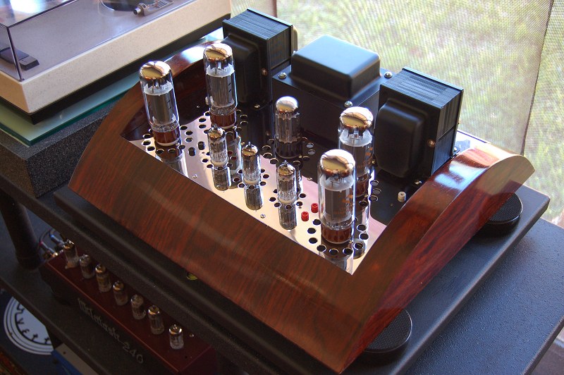
The metal chassis slides into the wood cabinet.
I still need to veneer the cabinet here and then it was time to get back to wiring.


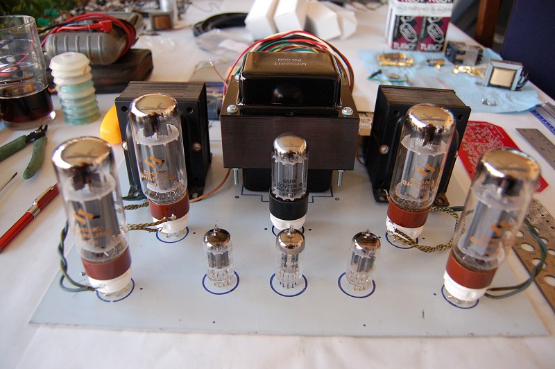
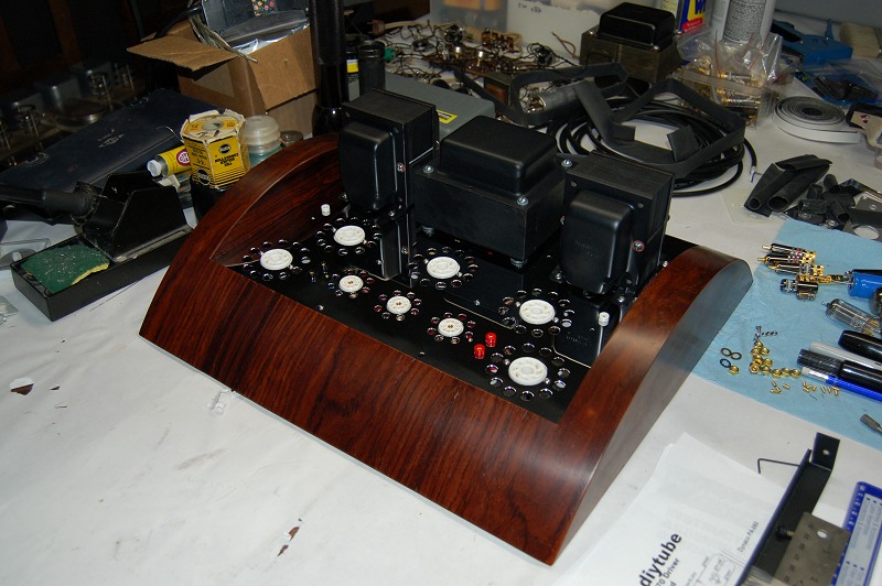
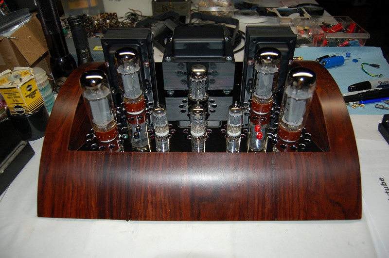
Here are a few competed pics with and without tubes.

I want to acknowledge Craig Ostby with NOSValves.com
His help with this build has been invaluable.